Introduction
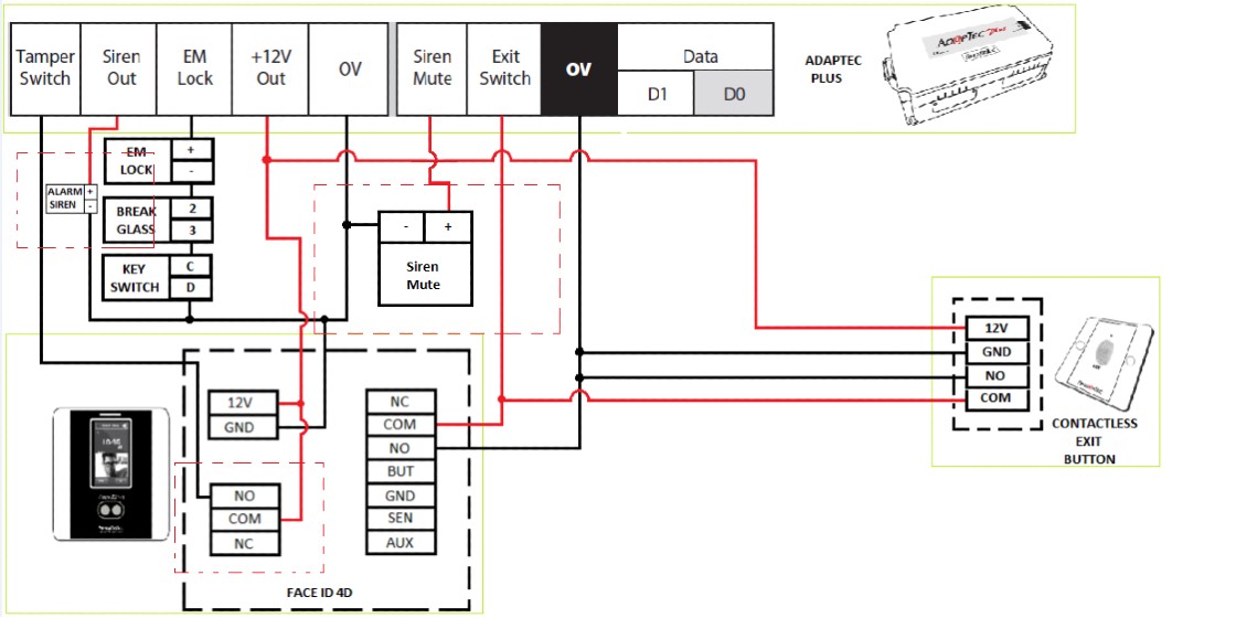
FingerTec Face ID 4D is now supplied with a new version of the coreboard (FMM) that comes with new hardware parts and new exterior parts. To ensure the reader connects with secured wiring, we suggest using the AdapTec Plus connection. Using AdapTec Plus can easily prevent someone from breaking into the premise.
Requirements
· Face ID 4D
· AdapTec Plus
· Contactless exit button
Wiring diagram
Setup External Siren
Requirements
· External siren 12VDC
· Power Supply AdapTec Plus
· Face ID 4D reader
· Switch (siren mute)
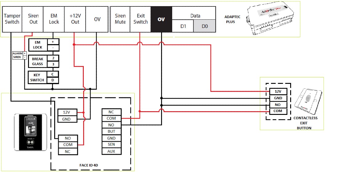
Wiring diagram
- Follow the diagram above for a wiring connection to install an external siren.
Please also make sure to connect the siren mute switch to stop the external siren.
- If you are using a 240vac external siren. You need to add relay connect with NO/COM from the device.
How to Setup Siren from Device
· Go to Main Menu – Select Personalize – go to Bell Schedules – choose Options – click External Bell Relay – tick on NC2
· Please make sure if you set Bell Schedule, don’t forget to change Repeat = ‘Never’ to the day you want to set the Schedule Bell.
Note: If some of the screenshots or steps viewed here are different from the ones in the current system, this is due to our continuous effort to improve our system from time to time. Please notify us at info@timeteccloud.com, we will update it as soon as possible.
Introduction
Good news, FingerTec has launched Face ID 5 recently, and the two new models that are equipped with temperature readers are Face ID 5 TD and Face ID 5 FTD that also can be used for building access control.
*Please state in your inquiries before purchasing the Face ID 5 with Access Push to be compatible with our software. This tip will show how the Face ID 5 can function as an access control system for in and out and pair with our R3c device.
Process
Diagram 1 : Connection of Face ID 5 with AdapTec Plus & R3c
Diagram 2 : Connection of Face ID 5 with R3c
Face ID 5 settings at the device for Access control
Picture 1 : Press Menu Icon
Picture 2 : Select COMM icon
Picture 3 : Select Serial Comm
Picture 4 : Select Serial Port
Picture 5 : Select Master Unit
After setting the Face ID 5 as a Master Unit, the IN and OUT for the device need to be set as to determine either the master will act as the IN device or OUT.
Picture 6: Push menu icon
Picture 7 : Select Access Control
Picture 8: Select the Master device and Slave device for position for ether In or Out
Picture 9 : Master Device select In or Out
Picture 10 : Slave Device select In or OutNote: If some of the screenshots or steps viewed here are different from the ones in the current system, this is due to our continuous effort to improve our system from time to time. Please notify us at info@fingertec.com, we will update it as soon as possible.
Introduction
AdapTec Plus and AdapTec X has a siren function to pair with a master device to enhance the alarm sound signal from a master device. This siren will go off when a master device sends a signal such as a door open, a device broken, etc (depends on types of master) to AdapTec Plus and Adaptec X.
Process
FingerTec Remote Control Door Switch has two channels to mute the triggered alarm at AdapTec Plus and AdapTec X Siren and Exit Switch. Exit Switch using Remote Control Door Switch is easier for users because they can control door access remotely without needing long wiring for the exit button. Hence, receptionists can open the door for authorized people remotely.
Connection above is for internal siren for AdapTec Plus or Adaptec X only. For more sound coverage, an additional external siren 12VDC can be added.
Note: If some of the screenshots or steps viewed here are different from the ones in the current system, this is due to our continuous effort to improve our system from time to time. Please notify us at info@fingertec.com, we will update it as soon as possible.
Introduction
The TA100C (FMM) is a
biometric terminal for time attendance that includes an internal siren and
allows the connection of external sirens for an effective alarm system. This
system can also be scheduled to signal events within the working schedule such
as starting work time or end of break. The two types of sirens that can be
connected to the TA100C (FMM) are:
- 12Vdc for small
industries or office use
- 240Vac for big
factories with a noisy environment
To compensate for the
additional power required for the external sirens, the Adaptec TA can be used
as a power supply and backup in case of power failures, ensuring that your
alarm system is always running.
Benefits
Connecting your terminals to
the Adaptec TA ensures a stable and reliable power source for your system to
operate at optimum capacity. By connecting the terminal and external siren to the
Adaptec TA, the internal relay of the terminal will be protected from the high
voltage. If the voltage is too high, the fuse in Adaptec will break the
circuit, thus protecting the internal components of the terminal.
Adaptec TA has 2 power sources, 5VDC and 12VDC and you can
connect any of FingerTec terminals to Adaptec TA by selecting the correct
voltage. It also comes with a backup power in case of power failure.
Process
To connect the external siren to the terminal, follow the
steps below.
1. Open
the back casing of the TA100C (FMM) terminal.
2. Plug
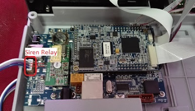
in the connector of the external siren into the MCU Board.
3. Follow
the wiring diagram to connect the terminal to Adaptec TA.
4. Change
the External Bell Relay settings in the terminal device itself.
Go to Menu > Personalize > Bell Schedule
> Options > External Bell Relay > NC2
5. To
add a new bell schedule, go to Menu > Personalize > Bell Schedules >
New Bell Schedule > Set
the option accordingly:
·
Bell
Status: To turn the bell on or off.
·
Bell
Time: Set the time for the bell to ring automatically.
·
Repeat:
Set the bell to repeat on certain days or every day.
·
Bell
Type: You can set for the bell to be triggered from the internal bell or from
an
external bell that is wired to the device.
·
Ring
Tone: Select your preferred ringtone that will emit from the bell.
·
Internal
Bell Relay: Specifies the time duration for the alarm to ring (ranges from 1s
to999s).
·
External
Bell Relay: Specifies the time duration for the alarm to ring (ranges from 1s
to999s).
With AdapTec Plus, you can unlock a
door easily by using a remote control. Pair your door remote control with
AdapTec Plus to use this feature.
Below is the wiring diagram showing
you how to do it.
The siren
output signal from a FingerTec device is known as a dry contact and this
basically means that the signal is not initially connected to a voltage
source. It can also be referred to as a secondary set of contacts of a relay circuit, which does not make or break the primary current that is being controlled by the relay. Selected FingerTec devices that come with a siren include TA100C, AC100C, TimeLine 100 and other time attendance systems.
Previous
installations to connect a siren with a FingerTec device could only support DC12V
sirens. Now, AC240V sirens, which emits a louder sound compared to the DC12V siren, can be used in the installation provided that the relay used to control a circuit between the FingerTec device and
siren supports the appropriate voltage. A power supply, such as
AdapTec Plus for example, is required and must also be compatible with the relay in
order for the connection to be successful.
The
following installation diagram will guide you on connecting a FingerTec
device to an AC240V siren with the use of a relay board and power supply.
With this in place, there is now an option provided for you to select the siren that suits your implementation better, be it a DC12V or AC240V siren.
By using 2 units of Face ID 2, users can now control door access on top of checking time attendance. We will be demonstrating how to connect 2
units of the Face ID 2 terminals to work as IN/OUT terminals. You will need to connect the 2 terminals together
according to the diagram below:
With the above
wiring, you can now have access to enter and also exit from the same door using the
2 units of Face ID 2. Voila!
Initiated and written by: SF Lim
The most noticeable difference between the 2 AdapTec Plus is the significant weight difference. Almost half the weight lighter compared to its predecessor, the new AdapTec Plus is able to support the NO setting for the door lock accessories such as door strikes and electromagnetic locks. It also has a brand new buzzer feature that works as an indicator every time a door is unlocked, or if there is too high a power input to the AdapTec Plus.
There are a few features that installers would find helpful as well, such as the LED light indicators. There are three LED lights in the AdapTec Plus that indicate to the user that the door lock is working, that the AdapTec processor is in good condition, and that the battery needs to be replaced.
For more information on the features of the new AdapTec Plus, click here.
Initiated by Pang
Written by Vincent
With the recent release of our new product AdapTec Plus, many might wonder what is the role of AdapTec Plus in supporting the terminal. The AdapTec plus is a combination of a power supply with enhanced access control functionalities. It supports FingerTec’s encrypted 26-bit Wiegand communication output; providing enhanced security level for extra protection. With the data encryption, the life span of the terminals can be prolonged without the risk of short-circuiting.
The H2i’s firmware has been updated to work with the AdapTec Plus. The latest firmware is available for download here.
To assist our resellers further, we have prepared a simple step-by-step instruction to guide you through the setup of connecting the H2i with the AdapTec Plus.
Connecting the H2i to the AdapTec Plus
To connect the H2i to the AdapTec Plus, please refer to the below diagram.
Updating the H2i to send an encrypted Wiegand output signal
By using the FingerTec Terminal Functions Update Tool v1.6, we can configure the H2i to send an encrypted Wiegand output signal to the AdapTec Plus.
1. Download the FingerTec Terminal Functions Update Tool v1.6 here.
2. Unzip the file and start up the FingerTec Terminal Functions Update Tool v1.6
3. Insert the IP address of the terminal and click Connect
4. When the connection is successful, the General and Access Control tab is will be accessible.
5. Click the Access Control tab and tick the checkbox for AdapTec Plus.
6. Click
Update to update the new feature into the H2i.
7. When the update is completed, click
Restart to restart the H2i.
Your H2i will now be able to work with the AdapTec Plus. If you are still facing problems with this process, kindly contact
support@fingertec.com for further assistance.
Initiated by: Henry Pang
Written by:Vincent Chan