

How To Setup TimeTec BLE-2 Without Modifying The EM-Lock Wirings

Introduction
In this link, we’ve described how to add TimeTec BLE-2 onto existing FingerTec Device. However, we received some feedbacks on whether is it possible to retain the arrangements of the EM-Lock wiring connection as well. This is to prevent the need of a new wiring as well as to assist in cost-saving.
Process
Hence in this article, we will explain how to add TimeTec BLE-2 without modifying the EM-Lock wirings. For this case, we will only require 4 cables to set up the wiring :
1. Two cables for power cable: +12V and GND.
2. Other two cables for Channel 1 Output: OUT 1 and COM.
The Channel 1 Output from TimeTec BLE-2 will be connected to the Button Input at the device. Therefore, when users access the door via TimeTec Security App, the Channel 1 Output will in turn be triggered. This output will then send the signal to the device thus unlocking the door. Refer to the diagrams below for more information.
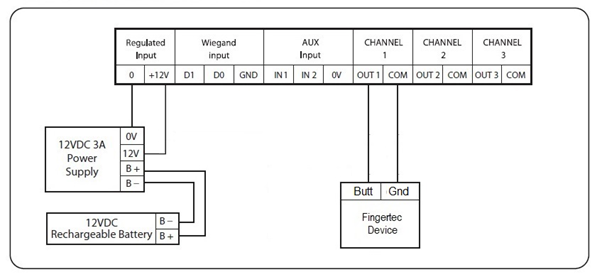
Picture 1: Wiring diagram from TimeTec BLE-2
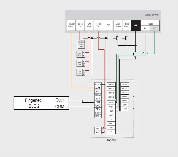
Picture 2: From TimeTec BLE-2 to FingerTec Device.
To use this connection, we need to set TimeTec BLE-2 to Normally Open (NO) mode. You can configure this setting by looking at the right side of TimeTec BLE-2 and slide up the switch to enable Normally Open (NO) Mode.
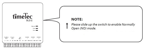
Picture 3 : Switch for TimeTec BLE-2 door lock type
Please take note that all transaction records from TimeTec BLE-2 are saved within TimeTec Security App only, and it will not be displayed on FingerTec Software or device.
Note: If some of the screenshots or steps viewed here are different from the ones in the current system, this is due to our continuous effort to improve our system from time to time. Please notify us at info@timeteccloud.com, we will update it as soon as possible.


0 comments:
Have any questions or inquiries about FingerTec? Drop your input here.